|
 |
||
|
|
|
||
|
|
Technical description of the BioWall
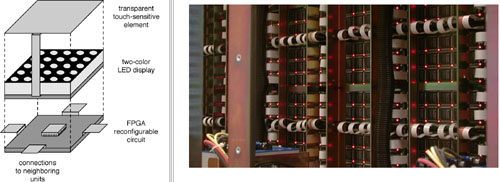
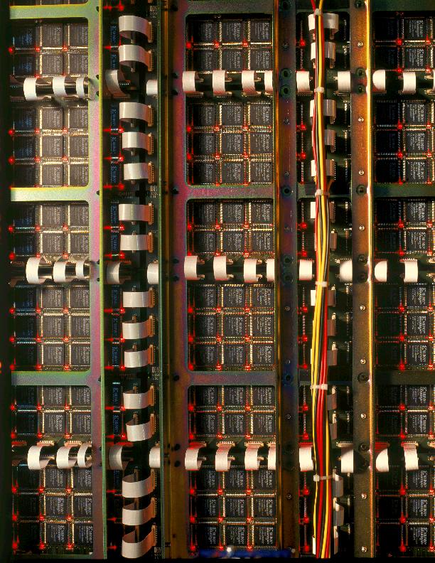
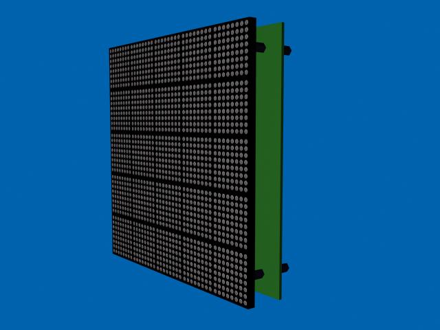
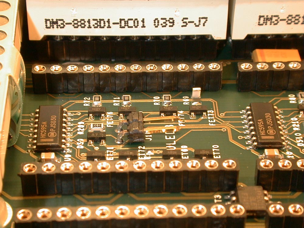
The main idea behind the construction of the BioWall is the realization of Embryonic machines. The structure of such machines, described in detail elsewhere is hierarchical: organisms (application-specific systems) are realized by the parallel operation of a number of cells (small processors), and each cell is implemented as an array of molecules (programmable logic elements). To implement this kind of machines, the BioWall is structured as a two-dimensional tissue composed of units (each unit corresponds then to a molecule), where each unit consists of an input element (a touch-sensitive membrane), an output element (an array of 8x8=64 two-color LEDs), and a programmable computing element (a Spartan XCS10XL Xilinx FPGA ).
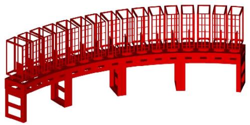
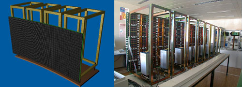
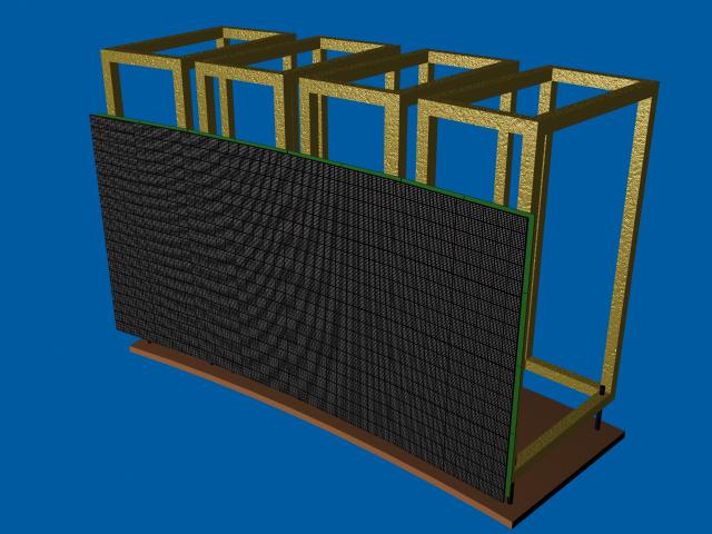
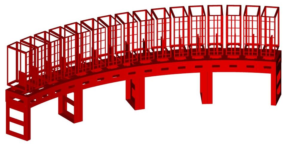
The BioWall is a perfectly scalable machine: prototypes ranging from 150 (10 rows of 15 units) to 3500 units (25 rows of 140 units) have been realized and tested. The tissue represents then an impressive amount of computational power (up to 3500 FPGAs), coupled with an I/O interface (the membranes and the LED arrays) that allows a large-scale visual and tactile interaction. The advantages of this solution are obvious: on one hand the size of the display allows an immediate interaction with applications that are normally limited to software simulation on a computer screen (some of these applications are described in the next section, others are mentioned in the conclusion), and on the other hand the computing power and programmability of the FPGAs allow the prototyping of new bio-inspired systems.
For the moment, the Xilinx
FPGA can only be programmed with the same configuration, which limits
the functionality of the units to the 10,000 equivalent logic gates
of the Spartans, while the considerable delays inherent in propagating
a global signal over distances measured in meters limit the clock
speed to a few hundred KHz (a speed that is nevertheless more than
adequate if coupled with the massive parallelism of the machine
and considerably too fast for human interaction in many applications).
The software tools developed for the BioWall are rudimentary but complete. A simple interface on a PC allows the user to define a set of files that will be used to configure the tissue. Four kinds of files are currently defined (more can be added): the configuration file for the Xilinx FPGAs, and three different formats used to send user-defined data on the input pins at the borders of the tissue (used, for example, to provide an initial configuration for a cellular automaton). The values on the output pins at the borders of the tissue can be read by the PC and either stored on disk or used as required. Resources
|