This chapter will describe our approach to the design of a self-repairing FPGA. Section 4.1 will provide a detailed description of MuxTree, the multiplexer-based FPGA we developed to implement the molecular level of our ontogenetic system. Section 4.2 will discuss the problem of self-test, an essential preliminary to self-repair. Section 4.3 we will proceed to describe the reconfiguration mechanism we adopted to implement self-repair, and introduce a modified self-replication mechanism, containing a set of novel features to provide support for self-repair. In the last section (section 4.4) we will provide a simple (but complete) example of the behavior of our FPGA in the presence of faults.

MuxTree is no exception to this rule, but is unusual in that it is remarkably fine-grained: the programmable function is realized using a single two-input multiplexer (Fig. 4-2). The multiplexer being a universal gate (i.e., it is possible to realize any function given a sufficient number of multiplexers), the first requirement for an FPGA element is respected. Each element is also capable of storing a single bit of information in a D-type flip-flop, fulfilling the second requirement.
The programmable function is therefore realized by the single multiplexer M0. The two one-bit-wide inputs are programmable, and 6 bits of the element's configuration ( LS[2:0]for the left input and RS[2:0]for the right input) are used to select two of eight possible choices:
The source of the multiplexer's control variable is also programmable: a single bit of the configuration ( M) selects whether the value of EIBor that of EOB(both long-distance connections, as explained below) will control the multiplexer.
The output NOUTof the element can have two sources, depending on the value of configuration bit S. If the element is purely combinational, S=0and NOUTis the output of the multiplexer. If, on the other hand, the element is supposed to have a sequential behavior, S=1and NOUTpropagates the output of the flip-flop F.
The D-type flip-flop Fis therefore used to implement sequential behavior. Its purpose is to store the output of the multiplexer at the rising edge of a functional clock FCK, whose period depends on the application24. The configuration bit Iallows the user to define a default value for F, which will be restored by the initialization signal INIT.
The first (short-distance) network consists of the following connections:
Obviously, this short distance network, being fixed (i.e., not altered by the configuration of the element) imposes a certain pattern of communication: each element can access the output of its neighbors to the south, southeast, and southwest, and propagate its own output to its neighbors to the north, northeast, and northwest. This pattern, which might at first sight appear somewhat peculiar, has in fact a definite purpose, as we will explain below in subsection 4.1.4.
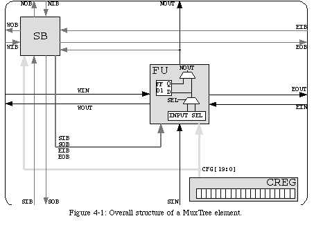
Of course, a fixed pattern to an FPGA's connections is a very restrictive limitation. In order to provide a way for communication to occur outside the fixed network, we introduced a second set of connections. This new network (dark gray in Fig. 4-1) is entirely separate from the first, and allows the output of an element to propagate beyond its immediate neighborhood.
The long-distance network provides one input and one output line in each of the four cardinal directions (in Fig. 4-1, SIB, NIB, EIB, and WIBare the four input lines, while SOB, NOB, EOB, and WOBare the corresponding output lines). The values propagated through these lines are selected in the switch block SB(Fig. 4-3), which is controlled by the element's configuration.
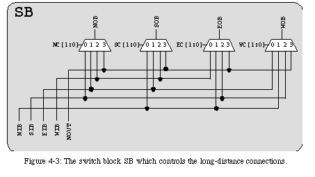
The purpose of the long-distance network is to propagate the output NOUTto destinations which are inaccessible through the short distance network. There, this value can be used as either an input to the multiplexer (though lines SIBand SOB) or as the multiplexer's control variable (though lines EIBand EOB).

The configuration of the circuit (i.e., the sum of the configurations of all the elements) is propagated within each of the blocks defined by the self-replication mechanism: all the registers are chainedtogether to form one long shift register following a path determined by the block's membrane (Fig. 4-5). The circuit's configuration can thus be seen as a serial bitstream which follows a predetermined path to fill all the elements within a block.
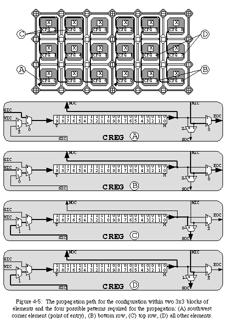
Careful observation of the programmable network should reveal that a set of 4 communication patterns (i.e., four sets of values for the variables S0through S3) can describe the propagation path through any block (Fig. 4-5).
The structure of MuxTree does not allow us to determine a precise figure for the time required to completely configure an array of elements. In fact, the speed of the propagation, and thus the time required for the configuration of the FPGA, depends on the clock which controls the register. Whereas in conventional FPGAs the maximum frequency of this configuration clockis independent of the application, such is not the case for MuxTree. The maximum clock frequency depends essentially on the longest combinational path the configuration signal has to traverse. In conventional FPGAs, the configuration propagates though a fixed path, and the frequency can thus be determined independently of the configuration itself. In MuxTree, the propagation path for the configuration depends on the size of the blocks, and thus on the application.
We cannot therefore determine a priorithe maximum frequency of the configuration clock. On the other hand, we can assume that the configuration register will be able to operate at a much greater frequency than the flip-flop used in the element's functional unit. Therefore, we will assume that there exists in our system a configuration clock CCK, distinct from the functional clock FCK, and operating at a much higher frequency.
A binary decision diagram [4, 16, 57] is essentially a compact representation of a binary decision tree, which in turn is a means to describe combinational functions. If the minimization of binary decision diagrams is a complex problem, deriving the binary decision tree for any given combinational function is trivial. In other words, it is very easy to find abinary decision diagram which realizes a given function, but it can be very hard to find the minimaldiagram for a function
Nevertheless, BDDs remain a powerful representation method for combinational functions, and MuxTree was designed to directly implement such diagrams: the functional unit of a MuxTree element is patterned after the basic unit of BDDs, the test element (Fig. 4-6). A test element represents a choice: if the test variable Sis 0, then the output Owill be equal to the input I0, else (if S=1), Owill be equal to I1.
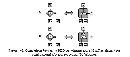
It should be obvious that the behavior of a test element is identical to that of a two-input multiplexer controlled by the variable S, that is, identical to that of the functional unit of a MuxTree element. A slight complication is introduced by the need for sequential behavior ("standard" BDDs are exclusively combinational), but the transition from the description of a function, through a BDD representation, to a MuxTree configuration remains relatively effortless26 .
The desire to model BDD test elements then explains many of the peculiar features of MuxTree. In particular, the unusual pattern of short-distance connections is designed to simplify the task of bringing the inputs to the test element, and the set of programmable inputs to the functional unit was selected to allow it to implement all possible configurations of a BDD test element (Fig. 4-7).

An accurate model for physical faults is a prerequisite to the analysis of any testing method. Unfortunately, such a definition is far from simple, and fault modeling remains a subject of considerable research efforts. Apart from design errors, which, strictly speaking, cannot be considered actual faults (but nevertheless require testing, if only at the prototype stage), physical faults can occur for a number of different causes. Among the more common such causes, we can mention fabrication defects (more and more frequent as fabrication technology improves), electron migration, cosmic radiation (relatively minor on the surface of the earth, but a major cause of concern when designing circuits for space applications), and various environmental factors (heat, humidity, etc.). Moreover, whatever their cause, these faults can have many different effects on the physical substrate of a VLSI circuit, such as increased delays on signals, bridges between lines, or broken connections. To further complicate the design of a testing system, the possibility of multiple faults occurring within a single circuit, as well as the transient or intermittent nature of many physical defects, should be taken into consideration.
In theory, a complete testing system should be able to handle all possible faults in a circuit, whatever their origin or effect. In practice, the sheer number of different possibilities prevents such a complete coverage. The conventional approach to the design of testing systems consists of handling faults from the point of view of their effect on the logic behavior of the circuit. In particular, the most common modelization of physical defects is as stuck-at faults: the only defects which are actually considered are those which have the net effect of fixing the value of a line to 0 (stuck-at-0faults ) or 1 (stuck-at-1faults). This model, which by no means covers all possible electrical faults in a circuit (for example, it does not accurately model physical faults which cause lines to be left floating in a high-impedance state, or faults which cause bridging between lines), is nevertheless the most commonly used in the development of testing algorithms27.
Because of the wide variety of fault models and of approaches, a complete classification of testing methods is extremely difficult. In the following paragraphs, we will classify testing approaches according to two criteria: off-line vs. on-line testing, and external vs. self-testing. The first classification is based on whether the test occurs while the circuit is operating (on-line test) or in a separate, dedicated phase (off-line test). The second criterion addresses the difference between circuits where the logic required for testing resides within the circuit itself (self-test) and those which rely on external devices (external test). This classification, however incomplete (see [1] for a much more exhaustive effort), will be useful to place our own testing mechanism in the framework of the test of digital circuits.
Off-line external testis by far the most common approach to testing digital circuits. This category includes a wide variety of techniques, applied both at fabrication and on the field. The advantage of testing circuits at fabrication, that is, before they are packaged, is that it is possible to access lines and elements in the interior of a circuit. Once a circuit is packaged, in fact, the only accessible points are the input/output pins of the chip. On the other hand, as long as the entire circuit is accessible, special machinery (e.g., bed-of-nails systems, electron beams) can access any line in the circuit to read or, in some cases, set its logic value.
Whenever it becomes necessary to test the circuit on the field, where only the input/output pins can be accessed, other off-line external testing techniques exist. The most frequently used approach is to apply a set of dedicated input patterns and observe the corresponding outputs of the circuit. These outputs are then compared to a set known to be correct28 , any discrepancy revealing the presence of a fault. The main advantage of such a technique is that, obviously, no additional logic is required inside the circuit, a major bonus for commercial applications. The drawbacks are that this kind of test is usually fairly time consuming (due to the number of input patterns required to test all or most of the lines in the circuit), that it can be difficult to find a set of input-output patterns capable of detecting most or all faults (particularly for sequential circuits), and that can be very hard to identify the exact location of a fault in a circuit.
It is not simple to identify a technique belonging to the category of on-line external testing. Such a technique would require that the test occur while the circuit is operating, but using external devices. We are not aware of the existence of such a technique.
Off-line self-testis a relatively common solution for circuits which require testing on the field. By integrating additional logic in the circuit itself, it is possible to overcome some of the drawbacks of external testing (for example, by allowing access to some of lines and elements in the interior of the circuit). Among the most common test techniques belonging to this category, we can mention the use of scan registers, where some or all the memory elements (flip-flops, registers, etc.) are chained together to form one long shift register, so that it becomes possible to retrieve a "snapshot" of the state of the circuit at any given time.
Another common off-line self-test technique is a variation of the I/O pattern approach used for external testing. In this case, the set of input patterns, rather then being stored outside the chip, is algorithmically generated (usually pseudo-randomly) inside the circuit itself. This kind of approach, while rarely guaranteeing that one hundred percent of faults will be found, is nevertheless able to detect the great majority of faults with a relatively small amount of additional logic. Often, however, most of the additional logic required by this technique is dedicated to the analysis of the output patterns: strictly speaking, self-test requires that the correctness of the outputs be verified within the circuit itself ( self-checkingcircuits), a task often more complex than the generation of the inputs.
The considerable amount of additional logic required by all on-line self-test techniques has prevented them from gaining a wide acceptance, particularly in the commercial world. Mainstream application do not require the ability to detect faults while the circuit is operating, since it is normally not vital that the correctness of the results be assured. Critical applications usually rely on duplication or triplication, where the outputs of two or three complete circuits are compared to detect faults. This approach, while it guarantees the detection of basically all single faults which can occur in a circuit, is nevertheless somewhat limited in its performance, as it cannot guarantee the detection of multiple faults.
On-line self-test techniques are usually developed anew for each circuit. It is therefore difficult to define a "standard" technique. In data paths, self-test is often implemented using error-detectingcodes [45, 47]: by using redundant bits to store information, it is possible to detect errors which alter the value of the data (the simplest method to achieve this kind of effect is the use of a single paritybit). In general, however, on-line self-test relies on the particular structure and functionality of each circuit to try and exploit distinctive features and properties to verify the behavior of the circuit. This lack of standard approaches is, of course, another reason for the rarity of commercial on-line self-testing circuits.
Thus, because of the relatively important hardware overhead, self-test has, until recently, been considered too expensive for extensive use in mainstream commercial applications. In particular, on-line self-test, while routinely applied in software, is very rarely exploited at the hardware level. Conventionally, circuits are subjected a non-exhaustive off-line test after fabrication so as to eliminate obviously faulty chips (quality assurance), and many faults are detected only when the circuit fails to operate correctly, at which point it is replaced. However, as circuits become more and more complex (implying an increase in the probability of faults being generated during fabrication) and expensive to manufacture, some basic self-test techniques are starting to be integrated in their design and quickly becoming indispensable.
While it is unlikely that on-line self-test will soon become a regular feature for mainstream applications, critical applications (e.g., circuits which operate in space, some embedded circuits such as those used for automotive applications, etc.) are likely to exploit such techniques at least to some degree since, unlike the simple duplication of the circuit, they can allow circuits to operate in the presence of more than one fault with an often smaller amount of additional logic.
This kind of consideration also applies to FPGA circuits. As they are often used for prototyping, commercial FPGAs (e.g., the Xilinx XC4000 series [111], the Altera FLEX series [6], and most others) often include some form of self-test, usually in the form of a boundary scanmechanism (a scan register limited to the input/output pins of the chip), meant to aid in the debugging of novel designs. However, as they become more and more complex (FPGAs have the potential of becoming some of the most complex circuits in the market), manufacturers are more and more interested in being able to detect faults not only in the designs being prototyped, but also in the circuits themselves. FPGAs developers are assisted in this task by the regular, modular structure of the arrays, as well as by the fact that they can be reconfigured so as to facilitate the detection of faults. Even further, the regularity of the arrays can also be exploited to achieve self-repair, the natural step beyond self-test.
The first added constraint is imposed by the need for self-repair: any self-repair mechanism will be able to know not only that a fault has occurred somewhere in the circuit, but also exactly where. Thus, our system has to be able to perform not only fault detection, but also fault location. Moreover, our self-repair mechanism, which, as we will see, uses spare elements to replace faulty ones and reroutes the connections accordingly, implies that certain kinds of fault (for example, faults on certain connections) are not repairable, as they prevent the reconfiguration of the array.
A second constraint is that we desire our system to be completely distributed. As a consequence, the self-test logic must be distributed among the MuxTree elements, and the use of a centralized system (fairly common in self-test systems) is not a viable option. This constraint is due to our approach to reconfiguration: by assuming that any element can be replaced by any other (an assumption which, as we will see, is a direct consequence of our self-replication mechanism), we need our array to be completely homogeneous.
The relatively small size of the MuxTree elements also imposed a constraint on the amount of logic allowed for self-testing. While the minimization of the logic was not really our main goal, and we did indeed trade logic in favor of satisfying our other constraints, we nevertheless made an attempt to keep the testing logic down to a reasonable size, which imposed some rather drastic limitations on the choices available for the design of our mechanism.
In addition to these constraints, more or less imposed by the features of our system, we also decided to attempt to design a self-test mechanism capable of operating on-line, that is, while the system is executing the application and transparently to the user. While biological inspiration was not, in this case, the main motivation behind our choice, such an approach is entirely in accordance with the behavior of biological systems: organisms monitor themselves constantly, in parallel with their other activities. This self-imposed constraint is extremely strong: to obtain an on-line self-test system while at the same time minimizing the amount of additional logic is a nearly impossible task. As a consequence, in our actual implementation this constraint was somewhat relaxed, and we will see that our self-test will occur on-line only partially.
In conclusion, we tried our best to respect the many external constraints, some of which contradictory, when designing our self-test mechanism. These constraints, and in particular the need for a completely distributed on-line mechanism, excluded the use of most of the "standard" approaches to self-testing (output pattern analysis, parity checking, redundant coding, etc.). The result is a system which falls somewhat short of our ideal requirements, but is nevertheless powerful enough for our purposes.
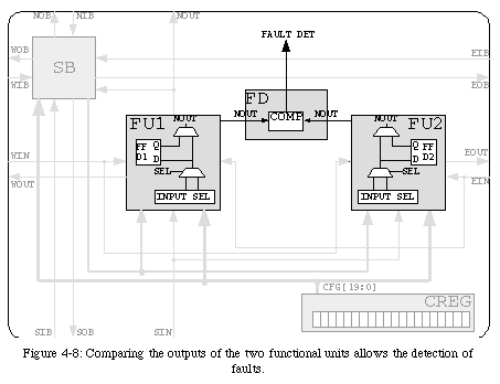
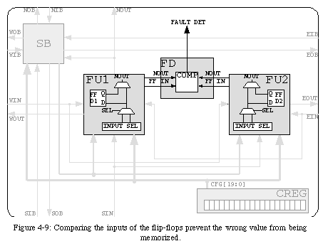
If our final objective was limited to the detection of faults, comparing the two outputs would be sufficient. However, a certain number of complications are introduced by the need for self-repair. As we will see in section 4.3, one of the requirements of self-repair is that the circuit be able to resume operation after being repaired without losing the information it stored at the instant the fault was detected. For an element configured as purely combinational, this requirement has no direct consequence: replacing the faulty element with a faultless one is sufficient to correctly repair the circuit. However, if the element's configuration requires the use of the internal flip-flop, it becomes necessary to keep faults from causing the incorrect value to be stored, which would corrupt the information held in the circuit and prevent the resumption of operation. To prevent the wrong value from being memorized, we must therefore introduce a further comparison between the inputs of the two flip-flops (Fig. 4-9).
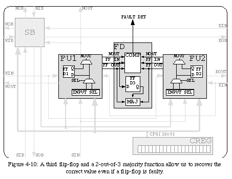
The desire to implement self-repair imposes a further addition to the self-test system. In fact, while two copies of the internal flip-flop are sufficient to detect the presence of a fault within the flip-flop itself, they cannot guarantee that the correct value will be used when repairing the circuit. Obviously, a difference between the outputs of the two flip-flops testifies to the presence of a fault (since their two inputs were tested, the fault must reside within one of the memory elements), but can not identify which one is faulty. In order to ensure that the repair mechanism will not access the wrong value, we were forced to introduce a third copy of the flip-flop (Fig. 4-10). A simple 2-out-of-3 majority function will then suffice to ensure that self-repair will indeed preserve the correct value.
An immediate solution to the problem of testing the connection network is to proceed as we did for the functional part, by using duplication. While not excluding the possibility of implementing either a partial or a full duplication29 , a practical observation associated with self-repair induced us to decide not to test the connection network. In fact, the only practical way to achieve rerouting in a simple network such as MuxTree's is to exploit the existing set of connections, a strategy which would not be possible without the assumption that the lines are indeed faultless. In other words, faults in the connection network might very well be detectable, but are not likely to be repairable.
Of course, we did not ignore the possibility of exploiting techniques other than duplication for testing the connection network. For example, we explored the possibility of reserving a certain portion of the clock period for testing: by propagating predetermined values through the network, it would be possible to detect faulty lines. This solution, which would probably impose a smaller (but still relatively important) hardware overhead compared to duplication (at the expense, of course, of an increase in the duration of a clock period), nevertheless still fails to address the question of repairability.
In conclusion, none of the mechanisms we examined was found to meet all our constraints, either because they imposed a considerable hardware overhead or because of unavoidable conflicts with the self-repair mechanism. As a consequence, we decided to temporarily desist in our attempts to design a self-test mechanism for the connections, while remaining fully aware of its importance and ready to investigate possible solutions.
As we mentioned, the constraints for the self-test of the configuration register are the same as for the rest of the element: the self-test mechanism must require a limited amount of additional logic, should ideally be on-line and transparent, and should be compatible with self-repair.
As was the case for the connection network, it is this last requirement which proved most restrictive. In fact, reconfiguring the array implies that a spare element will need to assume the functionality of the faulty one, and therefore its configuration. Since each element contains a single copy of the configuration register (its size precludes the possibility of duplication), a fault which modifies the values stored in the register results in a loss of information, which cannot easily be recovered30 . In addition, most of the faults which could affect the configuration register would prevent its operation as a shift register, thus requiring a separate mechanism to transfer the faulty element's configuration to the spare element. Such a mechanism, while in theory not excessively complex, would nevertheless require an unwarranted amount of additional logic.
An interesting observation which can have an impact on the development of a self-test mechanism for the register is that the configuration of an element is not supposed to change once the circuit has been programmed. While this observation does not address the question of repairability, it might simplify the task of fault detection: any change in the value stored in the register during normal operation must necessarily be the consequence of a fault.
Unfortunately, detecting such a change, while somewhat simpler than other detection methods, still requires too much additional logic to be viable31 . We feel that the hardware overhead could be vastly reduced by exploiting transistor-level design techniques, and plan to more closely investigate such approaches when we will have the opportunity to implement them32 .
So once again we were not able to find an approach which would satisfy all our requirements. Nevertheless, the probability of a fault occurring in the register being greater than for any other part of the element, we decided that some degree of testing was a necessity. Examining our system, we determined that relaxing the requirement that the self-test occur on-line would allow us to design an extremely simple mechanism.
Our approach is based on the observation that, when the circuit is programmed, the configuration bitstream is shifted into the register. It would therefore be very simple to include in the bitstream a header, in the form of a dedicated testing configuration. This header, which will be shifted into the register of all the elements in parallel, will not correspond to any particular functionality, but will rather be a pattern designed to exhaustively test that the configuration register is operating correctly. By using all registers in parallel we can make the length of the pattern independent of the number of the elements in the system, and by entering the pattern ahead of the actual configuration we can avoid the loss of information.
A pattern which meets our requirements (together with the gates required to detect the faulty operation of the register) is shown in Fig. 4-11. Its length corresponds to the length of the register to be tested plus one (the value of the input line used to propagate the pattern), and it is able to detect any defect in the operation of the shift register. The pattern ( 180001in hexadecimal notation) enters the configuration register as a "normal" configuration, i.e., it is shifted in from left to right. If no fault is present, the pattern's leading (right-most) 1 reaches the head Hof the register at the same time as the trailing 11 comes to occupy its tail T. The ANDgate will therefore output 1at the same time as the head of the register becomes 1, and the inputs of the XORgate, from 00, will become 11. Thus, at no moment does the output of the XORgate become 1, and thus no fault is detected.


In practice, however, there is no need for an additional mechanism to resolve this issue, as we can exploit existing material: by "chaining" the three flip-flops in the functional unit of the element to the shift register we can use the existing majority function to test the tail of the register (Fig. 4-14). This mechanism, which might appear exceedingly complex compared to the benefits it provides (the probability of a fault occurring in the last bit of the configuration register is, after all, relatively small), is in reality a requirement for self-repair. In fact, we introduced the third copy of the flip-flop in order to be able to transfer its value to the spare element, and chaining the flip-flops to the register is the most efficient approach to effect this transfer. The mechanism is therefore already in place and can be used for testing at no additional cost.
In conclusion, by relaxing the requirement that the detection occur on-line, we were able to design an extremely simple fault detection system (the hardware overhead consists of only two logic gates) which, as we will see, is perfectly compatible with self-repair.

In order to partially compensate for the limitations of self-test at the molecular (MuxTree) level, we plan to introduce further self-testing features at the cellular (MicTree) level. Since our ultimate goal is to use MuxTree as a programmable platform to implement arrays of MicTree cells, we hope that by combining the self-testing capabilities of the two levels we might be able to eliminate some of the weaknesses of each separate mechanism.
Self-test at the cellular level must operate under very different constraints. For example, since we are working with elements which are much more complex, we are not quite as limited in the amount of additional hardware we can introduce for testing, which in turn means that many approaches we had to discard because they were too complex could perhaps be applied. On the other hand, since the cellular level accesses the hardware only indirectly (through the configuration), certain kinds of faults are probably harder to detect, and self-test is unlikely to occur completely on-line.
Nevertheless, by integrating the self-test systems of the two levels, we hope to ameliorate the weaknesses of self-test at the molecular level. To this end, we have already experimented with a possible solution to the testing of a MicTree cell. This solution, conceptually similar to the method presented in [2, 95, 96], involves using half of the cells to test the other half, and then inverting the process. The test is effected fairly simply by adding a dedicated subprogram to the genome, accessed regularly by all the cells at the same time. While not strictly speaking an on-line self-test approach, this solution allows for transparent testing (the subprogram is invariant and can be added to any and all programs) with a limited amount of additional hardware, and is a valid complement to the molecular-level mechanism.
In commercial, off-the-shelf systems, fault tolerance is but rarely implemented through self-repair. For example, critical application usually rely on triplication: three copies of the complete system or circuit operate in parallel and their results are input to a 2-out-of-3 majoritycircuit which assures that the output will be correct even if one of the copies is faulty. Obviously this solution is considered a final resort, both because it is very expensive and because it allows for a relatively small degree of fault tolerance (two faults on two different copies of the system will invalidate the approach).
A second common approach to fault tolerance is the use of error-correcting codes [45, 47]. By using a redundant coding of information, it is possible not only to determine that a fault is present within a word (as was the case for the error-detecting codes mentioned in subsection 4.2.1), but also to recover the correct value. This increased versatility is achieved though the use of additional redundant bits, and is consequently more expensive in terms of additional logic. As for error-detecting codes, this technique is also ill-suited for fine-grained FPGAs, as it requires multiple-bit words.
Self-repair is a technique which achieves fault tolerance with a somewhat different approach. Rather than extracting the correct result from a faulty but redundant output, it aims at producing the correct output by removing the fault from the circuit. Since current technology does not allow the fault to be removed physically, self-repair relies on a reconfiguration of the circuit which reroutes the signals so as to avoid the faulty areas. This technique, while often capable of achieving considerable fault tolerance with a relatively small amount of additional logic, is obviously more complex to implement, as it requires both the ability of identifying the exact location of a fault in the circuit and the presence of redundant logic capable of replacing the functionality of the faulty part of the circuit. These requirements have the effect of limiting the practical use of self-repair to arrays of identical elements, where a faulty element it can be replaced by a spare which, being identical, can take over its functionality.
The amount of additional logic required by this approach can vary widely, depending not only on the number of the spare elements, but also on their placement within the array. In fact, the position of the spare elements, which can vary considerably from one implementation to the next, affects the complexity of the logic necessary to reroute the signals around the faulty elements. In practice, this kind of reconfiguration schemes are usually applied to arrays of complex processors, where the probability of faults occurring in the system justifies the relatively complex rerouting logic. Obviously, the regular structure of FPGAs is perfectly suited to this kind of approach, even if the small size of an FPGA element requires an important effort in minimizing the amount of rerouting logic, thus preventing the use of complex reconfiguration schemes. Nevertheless, reconfiguration is clearly the most suitable approach to introducing fault tolerance in an FPGA circuit.
As we mentioned, commercial fault-tolerant systems are exceedingly rare: systems capable of operating on the presence of faults imply in all cases a relatively important amount of redundancy, which is often considered wasteful for non-critical applications where VLSI chips or, more usually, circuit boards can be replaced without causing excessive problems for the user. In general, fault tolerance has not been considered a high enough priority to warrant the additional cost, with the possible exception of very large distributed systems where the sheer amount of circuitry involved considerably increases the probability of faults.
Introducing fault tolerance in single VLSI chips in general, and FPGAs in particular, has therefore been considered too expensive to be commercially viable. This outlook, however, appears to be changing. As circuits in generals, and FPGAs in particular, become more complex, their yield (i.e., the percentage of chips which exit the fabrication process without faults) is decreasing, and chip manufacturers are becoming more and more interested in being able to produce chips capable of operating in the presence of faults. FPGAs are ideally suited for this kind of approach, as their regular structure allows for the possibility of reconfiguration, and some of the leading manufacturers are beginning to seriously consider the option of introducing fault tolerance in their circuits [7, 8, 31, 85].
The extremely small size of our FPGA elements imposes a first set of very rigid constraints. As was the case for self-test, there are serious limitations to the amount of additional logic we can introduce to implement a self-repair mechanism. As we will see, this limitation has serious implications for the choice of possible reconfiguration schemes.
Our self-test system, in order to conserve the analogy with biological organisms, had to operate on-line. For self-repair, this restriction can be somewhat relaxed. Our self-repair can thus occur off-line, that is, cause a temporary interruption of the operation of the circuit (of course, the process should be as fast as possible). However, it is fundamental that the state of the circuit (that is, the contents of all its memory elements) be preserved through the self-repair process, so as to allow normal operation to resume after the reconfiguration is complete.
In practice, the only memory elements in our system are the configuration register and the flip-flop inside the functional part of the element. Since our self-test system allows us to test the register only during configuration, we can also limit its repair to the configuration phase. The assumption that the register is fault-free during normal operation is extremely useful for the reconfiguration of the array, and effectively reduces the requirement that the state of the circuit be preserved to the need to prevent the loss of the value stored in the flip-flops.
The requirement that the FPGA be perfectly homogeneous, which already had a serious impact on the choice of a self-test mechanism, also poses important restrictions on self-repair. Most, if not all, of the existing solution to the problem of repairing two-dimensional arrays rely on some form of centralized control to direct the reconfiguration of the elements. The need for homogeneity severely limits the reconfiguration algorithms which can effectively be adopted in our FPGA.
A final consideration on the desirable features of our self-repair system stems from an analysis of our self-replication process. As we have seen, the self-replication mechanism relies on the construction of an array of identical blocks of elements. It would obviously be desirable, if not strictly necessary, that the self-repair process also be contained inside each block. In other words, we would prefer that any reconfiguration occur within a single block of elements (and thus a single cell). This requirement is far from trivial, since it implies that the location of the spare elements be a function of the size of the block, which is programmable and thus unknown a priori. We will see that, by exploiting existing material (notably, the cellular automaton used to define the cellular membrane), we are able to fulfill this requirement with a remarkably small amount of additional logic.
On the basis of this observation, we can postulate that an efficient approach to designating a set of elements as spares would be to modify the self-replication mechanism to include such a feature. In order to introduce this feature, we modified our cellular automaton. The new automaton (Fig. 4-15, QT movie) is capable, at the cost of a relatively minor increase in hardware complexity, of performing two novel tasks:
For example, the particular automaton of Fig. 4-15 would define a block of 6x4 MuxTree elements, with one spare column for every two active ones.
Using the cellular automaton to define which columns will be used as spares is an extremely powerful concept. In fact, it allows us not only to limit reconfiguration to the interior of a block, but also to program the robustness of the system: by adding or removing spare column states to or from the sequence, we are able to modify the frequency of spare columns, and thus the capability for self-repair of the system. Without altering the configuration bitstream of the MuxTree elements, we could introduce varying degrees of robustness, from zero fault tolerance (no spare columns) to 100% redundancy (one spare column for each active column).
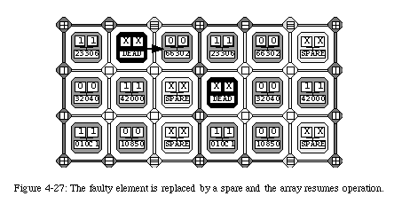
The mechanism we propose to repair faults relies on the reconfiguration of the network through the replacement of the faulty element by its right-hand neighbor (Fig. 4-16). The configuration of the neighbor will itself be shifted to the right, and so on until a spare elementis reached.
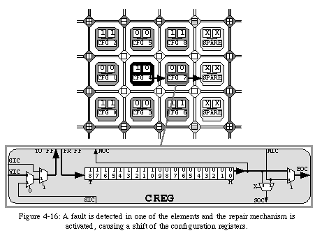
Once the shift is completed, the element "dies" with respect to the network, that is, the connections are rerouted to avoid the faulty element, an operation which can be effected very simply by deviating the north-south connections to the right and by rendering the element transparent with respect to the east-west connections. The array, thus reconfigured and rerouted, can then resume executing the application from the same state it held when the fault was detected (Fig. 4-17).
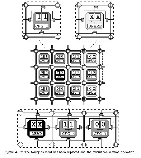
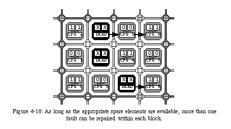
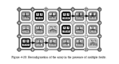
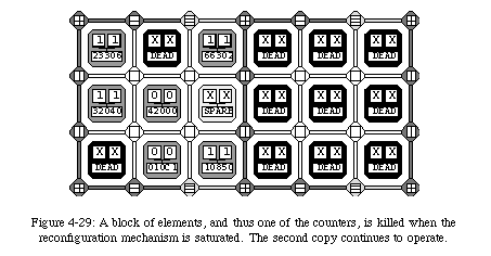
The reconfiguration of the elements through self-repair implies that all connections need to be rerouted to avoid the faulty element. Clearly, such an operation requires a relatively important amount of additional logic in the form of a set of multiplexers which select alternative connecting paths (Fig. 4-17). In order to minimize such additional hardware, we opted for limiting the reconfiguration to a single column. In other words, we do not allow the configuration of an element to be shifted more than once, which has the consequence of restricting the number of repairable faults to one per row between two spare columns. This limitation, while of course not trivial, is however alleviated by the fact that, as we have seen, the frequency of the spare columns can be programmed. Of course, all faults which do not conflict with this restriction can be repaired, leaving a considerable overall robustness to the system (Fig. 4-18).
The last relevant feature of our self-repair mechanism that we will mention is one that would apparently seem a disadvantage, but reveals itself to be a very positive feature to a more careful examination. We are talking about the fact that the entire self-test and self-repair mechanism we have described is volatile: powering down the circuit results in the loss of all information regarding the condition of the circuit. As we said, this might seem a disadvantage, since it forces us to find and repair the same faults every time the circuit is reconfigured. However, it is crucial to consider that by far the largest part of the faults occurring within a circuit throughout its life are temporary faults, that is, faults which will "vanish" very shortly after having appeared [23, 79]. It would therefore be very wasteful to permanently repair faults which are in fact only temporary, and the volatile nature of our mechanism turns out to be an important advantage.
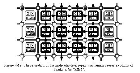
The choice to kill a column of blocks, which might seem arbitrary, is a consequence of the two-layer structure of our system: since a block is ultimately meant to contain one of our artificial cells, killing a column of blocks is equivalent to deactivating a column of cells (Fig. 4-20). At the cellular level, this event will trigger a recomputation of the coordinates of all cells in the system, that is, will activate the cellular-level reconfiguration mechanism. In other words, the robustness of the system is not based on a single self-repair mechanism, which might fail under certain conditions, but rather on two separate mechanisms which cooperate to prevent a fault from causing a catastrophic failure of the entire system.
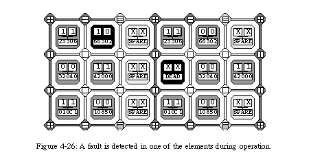
To prove the validity of our approach, we developed a prototype of our FPGA (which we called MuxTreeSR) in the form of a set of 18 interconnecting modules, each containing a single MuxTree element (see Appendix B). For demonstration purposes, we designed a simple application which we successfully implemented on our prototype: an up-down modulo-4 counter.
From the function's BDD we easily derived the configuration of the six elements required by this application (Fig. 4-21). The configuration of the modulo-4 counter consists of 6 active elements, four of which are purely combinational (the bottom two rows), while two are sequential (the top row), that is, make use of the internal flip-flop to store the current state of the counter. In addition, a single external input Iprovides the control variable which determines the direction of the counter: if I=0the circuit will count up (i.e., repeat the sequence 0-1-2-3-0...), while if I=1it will count down (i.e., 3-2-1-0-3...).
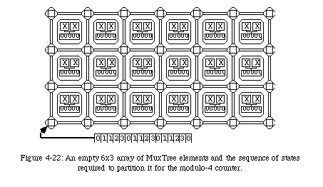
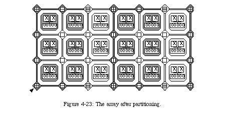
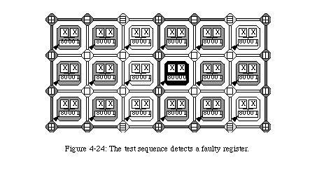
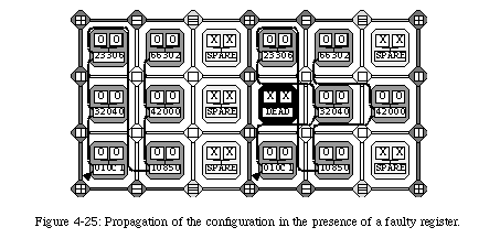
Once the six active elements have been configured (there is no need to provide a configuration for the spare elements, and thus no need to modify the bitstream depending on the frequency of spare columns), the circuit is ready to operate.
24.As in any electronic circuit, the maximum frequency in an FPGA depends on the longest combinational path in the array. Since the connections of an FPGA are programmable, the longest path changes with each configuration.
25.Which is not too surprising, since both are based on the now-defunct Algotronix family of FPGAs.
26.Which is a considerable advantage in relation to more "conventional" FPGAs, for which the transition from function to configuration can be extremely complex and time-consuming.
27.Of course, alternative methods exist. To name but one, IDDQ testing [80] tries to detect faults by monitoring fluctuations in the circuit's power consumption.
28.The comparison can either be effected on the complete output patterns or on a compressed version (signature).
29.Partial duplication would involve having two copies of the switch block, but a single set of connections, while full duplication would add a second, disjoint communication network (which, incidentally, would complicate fault location).
30.We considered the possibility of encoding the configuration using some form of self-correcting code (i.e., a redundant encoding which allows the correct information to be retrievable in the presence of a given number of faults), but after examining several options we concluded that all such codes would require an hardware overhead we deemed unacceptable.
31.A straightforward implementation would require N-1 XORgates to detect single faults in a N-bit register.
32.At the moment, we do not have access to a foundry: all the prototypes we developed exploited commercial FPGAs, and were therefore limited to gate-level design.
33.Or, more precisely, the output of the 2-out-of-3 majority function (Fig. 4-14). Note that for purely combinational configuration, shifting the value of the (unused) flip-flops is not strictly required. However, since disabling this feature would actually involve additional hardware, it is more efficient to simply let the mechanism assume that all flip-flops are in use.
34.The reconfiguration requires approximately 20 cycles of the configuration clock. If the difference between the frequency of the configuration clock and that of the functional clock is substantial, it is possible, and even probable, that the reconfiguration will occur transparently to the application.
35.Of course, we could also implement a single copy of the counter with two spare columns, which would maximize the robustness of the system, but would imply that two columns in our prototype would be "wasted".